BS (0.75-1.5kW 2P, Type А)

Channel Impeller BS (0.75-1.5kW 2P, Type А)

Solidpump BS series pump incorporates a channel impeller developed specially for sewage pumps. The impeller has a wide channel extending from inlet to exit, which prevents internal clogging by solids sucked in the pump.

Application

  • For wastewater discharge from industrial enterprises, shopping malls, hospitals, hotels
  • For domestic sewage and storm-water drainage from remote areas, parking lots and municipal facilities
  • For pumping of wastewater to sewage treatment plants
  • For pumping water at agriculture and aquaculture facilities


Technical Specifications

  • Insulation class : B (F on request)

  • Protection class : IP68
  • Water temperature: up to 40°C
  • PH: 6 to 10
  • Density of liquid : 1.3g/cm3
  • Power supply:
  • three phase 380V ±10%, 50Hz
  • single phase 220V ±10%, 50Hz
  • Motor protection: built in
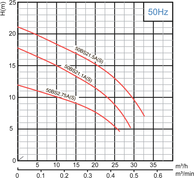
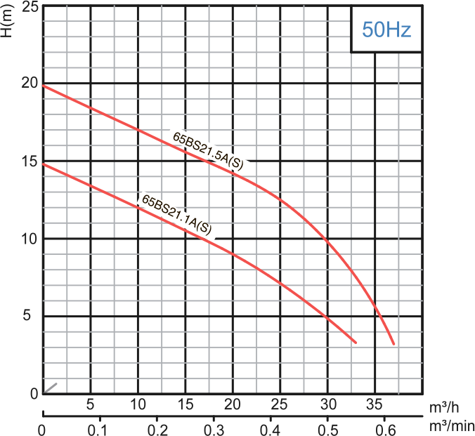
  • Capacity : up to 37m3/h
  • Head : up to 21 m
  • Maximum  immersion depth : 10m
  • Cable length : 8m

PERFORMANCE RANGE

Model
50Hz

Voltage

Current

Motor power

Outlet

Rated capacity

Rated head

Max capacity

Max Head

Impeller Passage

Cable


V

A

kW

HP

in

mm

m3/h

m

m3/h

m

mm

mm2

50BS2.75A

380

2

0.75

1

2

50

10

10

26

12

25

4G 1.0

50BS2.75SA

220

5.2

0.75

1

2

50

10

10

26

12

25

3G 1.0

50BS21.1A

380

2.8

1.1

1.5

2

50

8

15

29

18

20

4G 1.0

50BS21.1SA

220

7.2

1.1

1.5

2

50

8

15

29

18

20

3G 1.0

65BS21.1A

380

2.8

1.1

1.5

21/2

65

15

10

33

15

25

4G 1.0

65BS21.1SA

220

7.2

1.1

1.5

21/2

65

15

10

33

15

25

3G 1.0

50BS21.5A

380

3.2

1.5

2

2

50

8

19

33

21

20

4G 1.0

50BS21.5SA

220

10

1.5

2

2

50

8

19

33

21

20

3G 1.5

65BS21.5A

380

3.2

1.5

2

21/2

65

15

15

37

20

25

4G 1.0

65BS21.5SA

220

10

1.5

2

21/2

65

15

15

37

20

25

3G 1.5


Scroll

Model
50Hz

Voltage

Current

Motor power

Outlet

Rated capacity

Rated head

Max capacity

Max Head

Impeller Passage

Cable


V

A

kW

HP

in

mm

m3/h

m

m3/h

m

mm

mm2

50BS2.75A

380

2

0.75

1

2

50

10

10

26

12

25

4G 1.0

50BS2.75SA

220

5.2

0.75

1

2

50

10

10

26

12

25

3G 1.0

50BS21.1A

380

2.8

1.1

1.5

2

50

8

15

29

18

20

4G 1.0

50BS21.1SA

220

7.2

1.1

1.5

2

50

8

15

29

18

20

3G 1.0

65BS21.1A

380

2.8

1.1

1.5

21/2

65

15

10

33

15

25

4G 1.0

65BS21.1SA

220

7.2

1.1

1.5

21/2

65

15

10

33

15

25

3G 1.0

50BS21.5A

380

3.2

1.5

2

2

50

8

19

33

21

20

4G 1.0

50BS21.5SA

220

10

1.5

2

2

50

8

19

33

21

20

3G 1.5

65BS21.5A

380

3.2

1.5

2

21/2

65

15

15

37

20

25

4G 1.0

65BS21.5SA

220

10

1.5

2

21/2

65

15

15

37

20

25

3G 1.5


MATERIAL OF CONSTRUCTION

Item No.

Part name

Material

01

Hose coupling

Cast iron

01a

Hose coupling

Cast iron

02

Handle

Steel

05

Upper cover

Cast iron

06

Up-Bearing house

Cast iron

07

Bearing house

Cast iron

11

Motor body

Cast iron

13

Pump body

Cast iron

14

Impeller

Cast iron

17

Coupling adapter

Cast iron

22

Seat assembly

Cast iron

22a

Coupling seat

Cast iron

22b

Upper guide support

Cast iron

27

Stator


28

Rotor

Shaft : AISl304SS

30

Flange

Cast iron

31a

Bearing

Ball bearing

31b

Bearing

Ball bearing

32

Capacitor

(Single phase only)

33

Motor protector


34

Mechanical seal

SbCeramk:/CartJon.Cenm

35

Oil seal


47

Cable


Scroll

Item No.

Part name

Material

01

Hose coupling

Cast iron

01a

Hose coupling

Cast iron

02

Handle

Steel

05

Upper cover

Cast iron

06

Up-Bearing house

Cast iron

07

Bearing house

Cast iron

11

Motor body

Cast iron

13

Pump body

Cast iron

14

Impeller

Cast iron

17

Coupling adapter

Cast iron

22

Seat assembly

Cast iron

22a

Coupling seat

Cast iron

22b

Upper guide support

Cast iron

27

Stator


28

Rotor

Shaft : AISl304SS

30

Flange

Cast iron

31a

Bearing

Ball bearing

31b

Bearing

Ball bearing

32

Capacitor

(Single phase only)

33

Motor protector


34

Mechanical seal

SbCeramk:/CartJon.Cenm

35

Oil seal


47

Cable


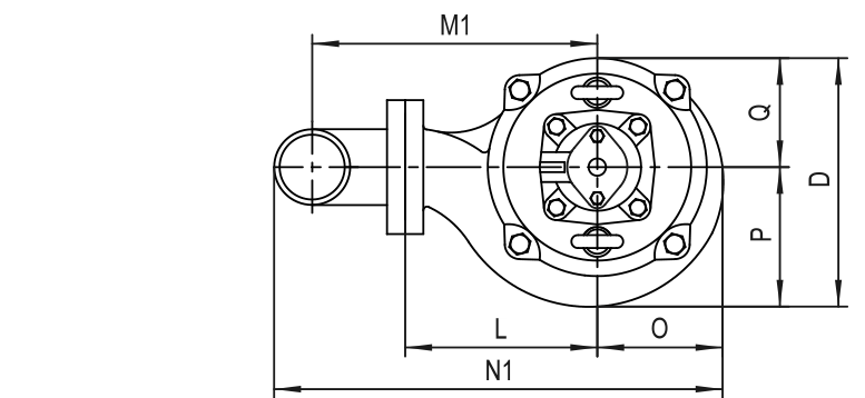
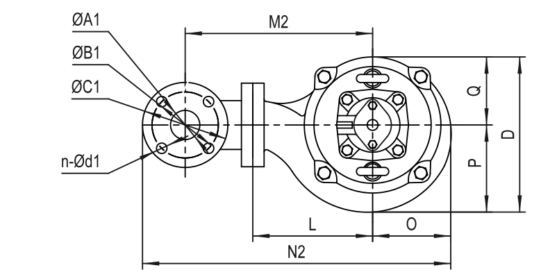
DIMENSIONS AND WEIGHT

Model

Ød

G

ØA1

ØB1

ØC1

n-Ød1

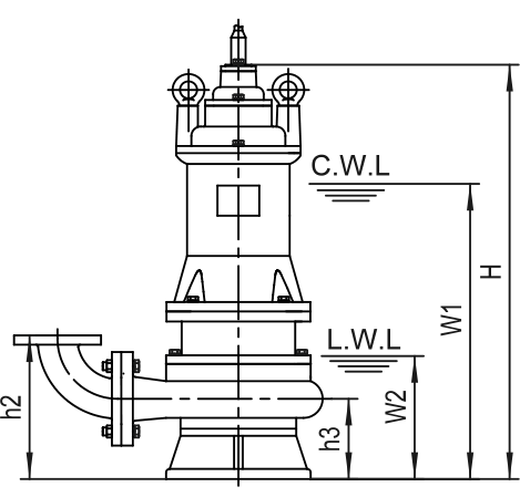
h1

h2

h3

W1

W2

H

O

P

Q

L

D

M1

M2

N1

N2

50BS2.75A

50

1½″

50

110

140

n-Ø14

200

195

95

300

120

450

94

96

94

130

190

195

225

315

388

50BS2.75SA

50

1½″

50

110

140

n-Ø14

200

195

95

315

120

450

94

96

94

130

190

195

225

315

388

50BS21.1A

50

1½″

50

110

140

n-Ø14

195

190

90

325

140

460

94

98

94

135

192

200

230

320

395

50BS21.1SA

50

1½″

50

110

140

n-Ø14

195

190

90

345

140

480

94

98

94

135

192

200

230

320

395

65BS21.1A

65

2″

65

130

160

n-Ø14

210

215

90

325

140

460

94

98

94

135

192

200

245

327

420

65BS21.1SA

65

2″

65

130

160

n-Ø14

210

215

90

345

140

480

94

98

94

135

192

200

245

327

420

50BS21.5A

50

1½″

50

110

140

n-Ø14

195

190

90

345

140

480

94

98

94

135

192

200

230

320

395

50BS21.5SA

50

1½″

50

110

140

n-Ø14

195

190

90

360

140

495

94

98

94

135

192

200

230

320

395

65BS21.5A

65

2″

65

130

160

n-Ø14

210

215

90

345

140

480

94

98

94

135

192

200

245

327

420

65BS21.5SA

65

2″

65

130

160

n-Ø14

210

215

90

360

140

495

94

98

94

135

192

200

245

327

420


C.W.L: Continuous running water level
L.W.L : Lowest running water level
Scroll

Model

Ød

G

ØA1

ØB1

ØC1

n-Ød1

h1

h2

h3

W1

W2

H

O

P

Q

L

D

M1

M2

N1

N2

50BS2.75A

50

1½″

50

110

140

n-Ø14

200

195

95

300

120

450

94

96

94

130

190

195

225

315

388

50BS2.75SA

50

1½″

50

110

140

n-Ø14

200

195

95

315

120

450

94

96

94

130

190

195

225

315

388

50BS21.1A

50

1½″

50

110

140

n-Ø14

195

190

90

325

140

460

94

98

94

135

192

200

230

320

395

50BS21.1SA

50

1½″

50

110

140

n-Ø14

195

190

90

345

140

480

94

98

94

135

192

200

230

320

395

65BS21.1A

65

2″

65

130

160

n-Ø14

210

215

90

325

140

460

94

98

94

135

192

200

245

327

420

65BS21.1SA

65

2″

65

130

160

n-Ø14

210

215

90

345

140

480

94

98

94

135

192

200

245

327

420

50BS21.5A

50

1½″

50

110

140

n-Ø14

195

190

90

345

140

480

94

98

94

135

192

200

230

320

395

50BS21.5SA

50

1½″

50

110

140

n-Ø14

195

190

90

360

140

495

94

98

94

135

192

200

230

320

395

65BS21.5A

65

2″

65

130

160

n-Ø14

210

215

90

345

140

480

94

98

94

135

192

200

245

327

420

65BS21.5SA

65

2″

65

130

160

n-Ø14

210

215

90

360

140

495

94

98

94

135

192

200

245

327

420


C.W.L: Continuous running water level
L.W.L : Lowest running water level

Movable Soft Pipe Installation (R)

Model

R

Y


N.W

G.W

Packing dimension

N.W

G.W

Packing dimension


kg

kg

mm

kg

kg

mm

50BS2.75A

22

23.5

490x225x240

24

25.5

490x225x250

50BS2.75SA

23

24.5

490x225x240

25

26.5

490x225x250

50BS21.1A

24

25.5

490x225x240

26

27.5

490x225x250

50BS21.1SA

25.5

27

515x255x240

26.5

29

515x255x250

65BS21.1A

24

25.5

490x255x240

28

29.5

490x255x250

Scroll

Model

R

Y


N.W

G.W

Packing dimension

N.W

G.W

Packing dimension


kg

kg

mm

kg

kg

mm

50BS2.75A

22

23.5

490x225x240

24

25.5

490x225x250

50BS2.75SA

23

24.5

490x225x240

25

26.5

490x225x250

50BS21.1A

24

25.5

490x225x240

26

27.5

490x225x250

50BS21.1SA

25.5

27

515x255x240

26.5

29

515x255x250

65BS21.1A

24

25.5

490x255x240

28

29.5

490x255x250

Movable Hard Pipe Installation (Y)

Model

R

Y


N.W

G.W

Packing dimension

N.W

G.W

Packing dimension


kg

kg

mm

kg

kg

mm

65BS21.1SA

25.5

27

515x255x240

29.5

31

515x255x240

50BS21.5A

26.5

28

510x255x240

28.5

30

510x255x240

50BS21.5SA

29

30.5

520x255x240

31

32.5

520x255x240

65BS21.5A

25.5

27

510x255x240

27.5

29

510x255x240

65BS21.5SA

28.5

30

520x255x240

32.5

34

520x255x240

Scroll

Model

R

Y


N.W

G.W

Packing dimension

N.W

G.W

Packing dimension


kg

kg

mm

kg

kg

mm

65BS21.1SA

25.5

27

515x255x240

29.5

31

515x255x240

50BS21.5A

26.5

28

510x255x240

28.5

30

510x255x240

50BS21.5SA

29

30.5

520x255x240

31

32.5

520x255x240

65BS21.5A

25.5

27

510x255x240

27.5

29

510x255x240

65BS21.5SA

28.5

30

520x255x240

32.5

34

520x255x240

Auto-Coupled Installation (Z)

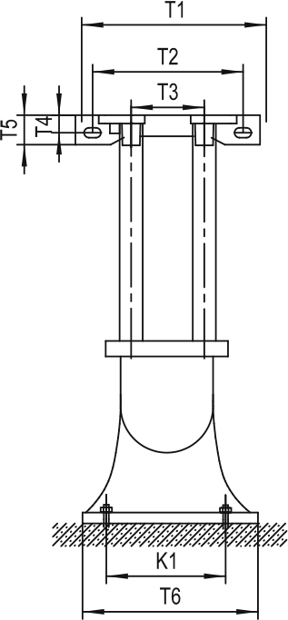
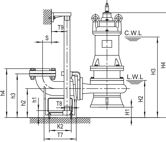
The coupling and pump will be packed individually, packing dimension and weight in table only refer to the pump, please refer to “Auto-Coupling” page to check coupling's packing dimension and weight.

Auto coupling

ØA

ØB

ØC

N-Ød

T1

T2

T3

T4

T5

T6

T7

T8

T9

K1

K2

S

h1

h2

h3

h4

50-50(PN6)

Ø50 / G2″

110

140

4-Ø14

265

215

105

25

42

200

215

15

67

165

135

63

25

160

250

280

C.W.L: Continuous running water level
L.W.L: Lowest running water level
Scroll

The coupling and pump will be packed individually, packing dimension and weight in table only refer to the pump, please refer to “Auto-Coupling” page to check coupling's packing dimension and weight.

Auto coupling

ØA

ØB

ØC

N-Ød

T1

T2

T3

T4

T5

T6

T7

T8

T9

K1

K2

S

h1

h2

h3

h4

50-50(PN6)

Ø50 / G2″

110

140

4-Ø14

265

215

105

25

42

200

215

15

67

165

135

63

25

160

250

280

C.W.L: Continuous running water level
L.W.L: Lowest running water level

Size table

Model

Auto coupling

H1

H2

H3

H4

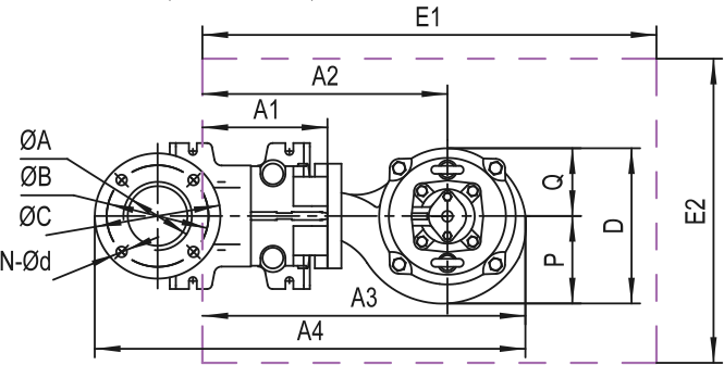
A1

A2

A3

A4

P

Q

D

E1xE2

Pump weight & packing dimension


N.W

G.W

Packing dimension

50BS2.75A

50-50(PN6)

65

185

365

515

155

285

378

510

96

94

190

650x550

20

21.5

490x225x240

50BS2.75SA

50-50(PN6)

65

185

380

515

155

285

378

510

96

94

190

650x550

21

22.5

490x225x240

50BS21.1A

50-50(PN6)

70

190

395

530

155

290

383

515

98

94

192

650x550

22

23.5

490x225x240

50BS21.1SA

50-50(PN6)

70

190

415

550

155

290

383

515

98

94

192

650x550

23.5

25

515x225x240

65BS21.1A

50-50(PN6)

70

190

395

530

155

290

383

515

98

94

192

650x550

21

22.5

490x225x240

65BS21.1SA

50-50(PN6)

70

190

415

550

155

290

383

515

98

94

192

650x550

22.5

24

515x225x240

50BS21.5A

50-50(PN6)

70

190

415

550

155

290

383

515

98

94

192

650x550

24.5

26

510x225x240

50BS21.5SA

50-50(PN6)

70

190

430

565

155

290

383

515

98

94

192

650x550

27

28.5

520x225x240

65BS21.5A

50-50(PN6)

70

190

415

550

155

290

383

515

98

94

192

650x550

22.5

24

510x225x240

65BS21.5SA

50-50(PN6)

70

190

430

565

155

290

383

515

98

94

192

650x550

25.5

27

520x225x240

Scroll

Model

Auto coupling

H1

H2

H3

H4

A1

A2

A3

A4

P

Q

D

E1xE2

Pump weight & packing dimension


N.W

G.W

Packing dimension

50BS2.75A

50-50(PN6)

65

185

365

515

155

285

378

510

96

94

190

650x550

20

21.5

490x225x240

50BS2.75SA

50-50(PN6)

65

185

380

515

155

285

378

510

96

94

190

650x550

21

22.5

490x225x240

50BS21.1A

50-50(PN6)

70

190

395

530

155

290

383

515

98

94

192

650x550

22

23.5

490x225x240

50BS21.1SA

50-50(PN6)

70

190

415

550

155

290

383

515

98

94

192

650x550

23.5

25

515x225x240

65BS21.1A

50-50(PN6)

70

190

395

530

155

290

383

515

98

94

192

650x550

21

22.5

490x225x240

65BS21.1SA

50-50(PN6)

70

190

415

550

155

290

383

515

98

94

192

650x550

22.5

24

515x225x240

50BS21.5A

50-50(PN6)

70

190

415

550

155

290

383

515

98

94

192

650x550

24.5

26

510x225x240

50BS21.5SA

50-50(PN6)

70

190

430

565

155

290

383

515

98

94

192

650x550

27

28.5

520x225x240

65BS21.5A

50-50(PN6)

70

190

415

550

155

290

383

515

98

94

192

650x550

22.5

24

510x225x240

65BS21.5SA

50-50(PN6)

70

190

430

565

155

290

383

515

98

94

192

650x550

25.5

27

520x225x240

This site uses cookies and related tracking technologies to personalize and enhance your experience on this site. By approving Privacy Policy you consent to the use of your personal data and cookies.